TRANSIENT RESPONSE OF ROTOR MODEL
1. BACKGROUNDS
2. EXAMPLES OF CALCULATIONS AND OUTPUTS – LINEAR SPRING SUPPORTS
2.2 EXAMPLES OF CALCULATIONS AND OUTPUTS – DAMPER SUPPORTS
1. backgrounds
|
1 – vibrator;
2 – case; 3 – clearance with oil
Nomenclature:
δ-clearance, m; e – orbit radius; ε=e/δ - eccentricity; ω- angle rotation speed; Ω- whirl speed; R- damper radius, m; L - damper length, m; μ– dynamical viscosity, Ns/m2; K – stiffness coefficient; C – damping coefficient |

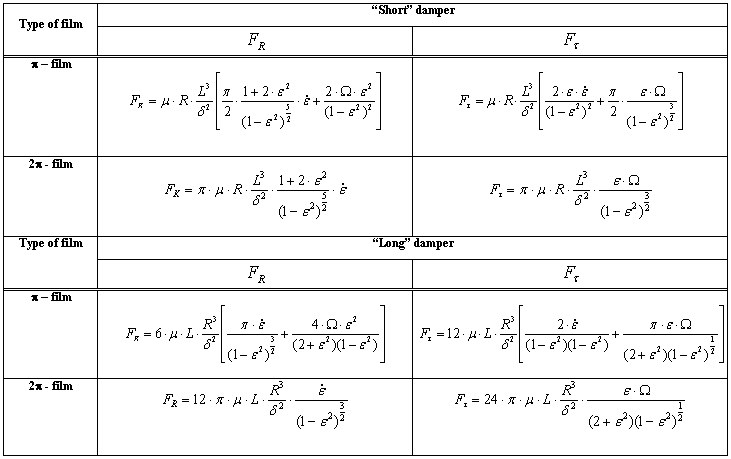
Table 1
Approximate models of the damper performances (laminar flow, = const)
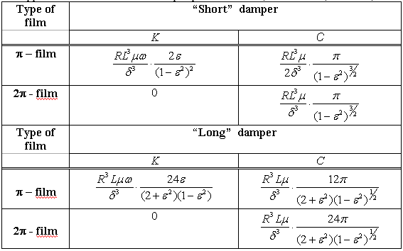

Fig. 2. Pressure distribution in squeeze-film damper
δ=0.228 mm; l = 12.7 mm; D=104.3 mm; μ=0.0217; n = 1000 rpm; ε=0.4
Reynolds boundary conditions
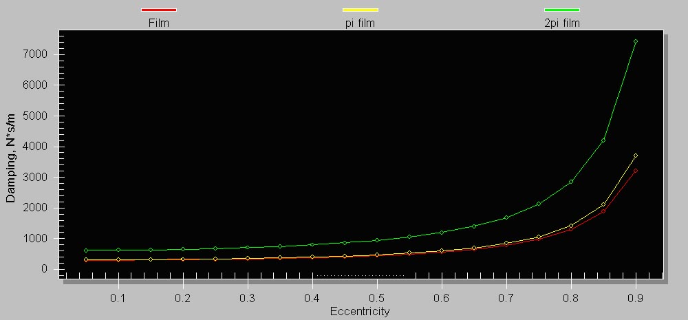
Fig. 3. Damping characteristics of squeeze-film damper
δ=0.228 mm; l = 12.7 mm; D=104.3 mm;μ =0.0217; n = 1000 rpm; ε=0.4;
Red line – Reynolds boundary conditions
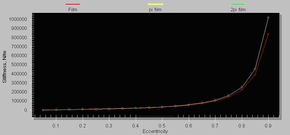
Fig. 4. Stiffness characteristics of squeeze-film damper
δ=0.228 mm; l = 12.7 mm; D=104.3 mm; μ=0.0217; n = 1000 rpm supports; ε=0.4;
Red line – Reynolds boundary conditions
Table 2 HYDRODYNAMIC FORCES (LAMINAR FLOW)