3.2.4 Approximate models of the damper performances
Sometimes the approximate models are useful for calculating the damper performances [ 6 ]. These models can be obtained from analytical solutions of the Reynolds equation at additional assumptions:
- The damper journal whirls within the spacing by circular orbits. If the damper design provides weight balancing the rotor wirls around the bearing axis, in other cases this assumption produces some uncertainty.
- The oil pressure distribution is symmetrical related to middle line of the damper active surface. For a "short" damper the pressure distribution is approximated with a parabola, for a "long” one - as constant.
- The cavitation film model is a p - film or 2p - film which are used for cavitation models. The first suits to cavitation zone is half of the curcle long, the second suits to absence of cavitation zone.
Calculation of the oil pressure in a sealed damper is performed for a "long" damper, for a not sealed one - as for a "short".
The damper stiffness K and damping C can be calculated out of pressure distribution for each eccentricity. Solutions [ 6 ] are given in the table 4.
Table 4
|
Type of film |
“Short” damper | |
|
|
K |
N |
|
p - film |
|
|
|
2p - film |
0 |
|
|
Type of film |
“Long” damper | |
|
|
K |
C |
|
p - film |
|
|
|
2p - film |
0 |
|


The "short" and "long" dampers solutions can be used for calculation of dampers performances at different boundary conditions.
Fig 11 illustrates some dampers layouts that can be calculated by the described algorythms. The layouts can be separated by two main features:
· presence of end seals,
· way of oil supply.
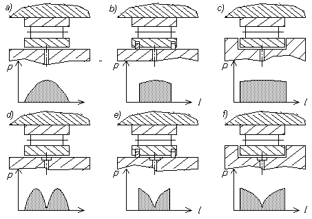
Fig 11. HDs layouts and oil pressure distributions
Version (a) is a damper without the end seals. The oil is supplied through one or a few orifices, the pressure distribution is described by a parabola.
Versions (b) and (c) have end cavitating regions, so the oil flow through the cavitating regions is not taken into consideration, the oil flow can be assumed as circular and the pressure as constant.
Versions (d), (e) and (f) differ from the upper ones by circular oil supplying grooves. Here the damper operating length is separated into two parts, each part having a distribution depending on cavitating regions. The table below gives combinations of features that permit to choose a calculating model for a particular layout, to choose a modelling factor to correct the hydraulic force and the length. For example a damper with a seal at the left end and witout seal at the right end one can be calculated by a "short" damper model with a doubled length and modelling factor 0.5.
|
Layout |
Type of damper |
Modelling factor |
Length of damper |
|
a |
short |
1 |
L |
|
b |
long |
1 |
L |
|
c |
long |
1 |
L |
|
d |
short |
2 |
L/2 |
|
e |
short |
1 |
L |
|
f |
short |
1 |
L |
Some calculation results confirmed by tests can be summarised as the following [ 3, 4, 6 ]:
· HDs up to 0.4... 0.5 eccentricity have constant damping coefficients;
· Cavitation zone area can be reduced by increase of the oil supply pressure;
· At uncavitied oil film under circular orbits and constant eccentricity the hydrodynamic stiffness diminishes.
· Damping in an uncavited damper (2p - film) is twice larger than in a cavitated damper (p - film).
· An uncavited HD needs an additional flexible element (a “squirrel-cage”) to bear radial loads.
· Completely cavitated HDs with unbalance parameters >0.5 always had dynamic transmissibility >1.
An uncentralised HD has a considerable nonlinearity, so final determination of its dimensions can be performed only by transient analysis including a rotor.
Final investigation of a HD performance and workability is to be performed in full-size test rigs or by engine tests.
![]()
![]()
![]()